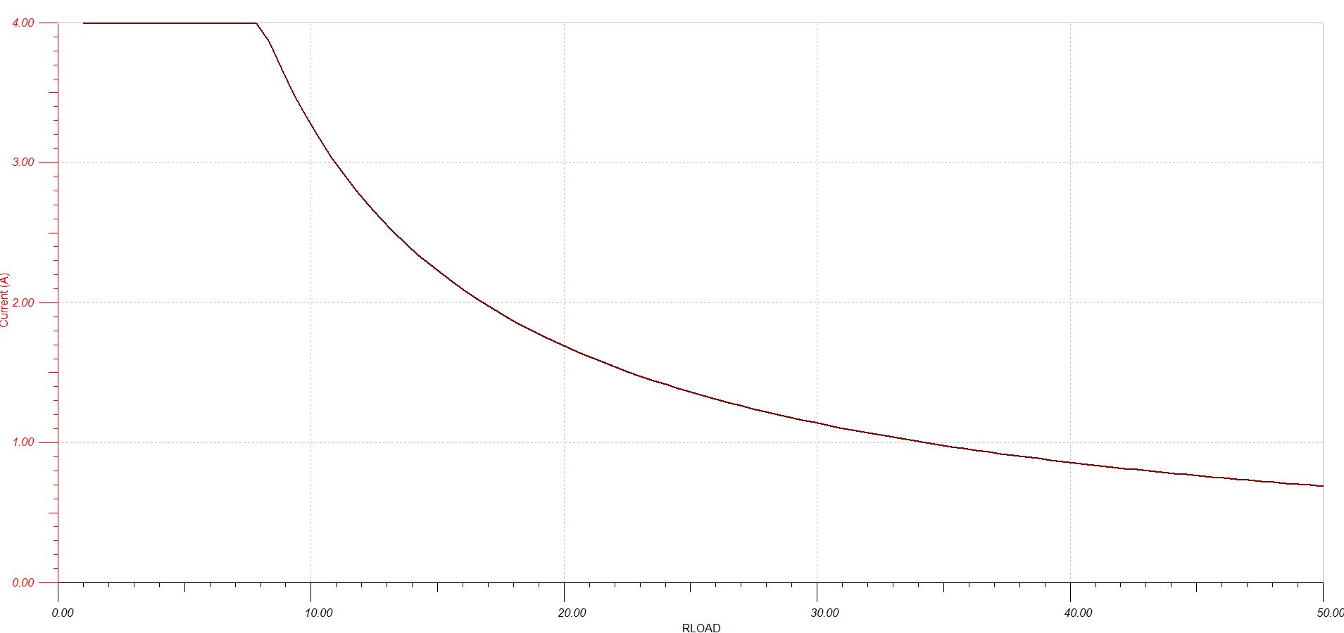
Current Limiter Offers Circuit Protection with Low Voltage Drop Circuit Diagram of the current from the base of Q1 and sends it to ground. This reduces Q1's collector current kee V ense t ping R1 to about 0.7V. The above circuit will act like a normal switch as long as the load doesn't try and draw too much current. If the load tries to draw too much current (50mA in this case) Q2 will divert some of the current away
Figure 3. A simplified circuit diagram of a dedicated current limiter IC. Limiting currents in a circuit is not a problem if suitable highly integrated ICs are used. It also makes sense to combine this type of circuit with a DC-to-DC converter if the converter doesn't have an adjustable current limiter. About The Authors
PDF Power Supply Current Limiting Circuit Diagram
Figure 1 shows a simple current limiting circuit. As the current through the two diodes in series begins to rise, they begin to conduct. This lowers the voltage at the base of the transistor and thus reduces the amount of current passing through the collector - emitter junction and subsequently to the output.
Current limiting circuits are essential to: Protect components from damage due to excessive current. Maintain circuit stability and prevent voltage drops. Ensure the safety of devices and users. Section 2: Common Types of Current Limiting Circuits. There are several methods to implement current limiting in electronic circuits: H2 2.1 Resistors Current Limiting Circuit Design Considerations. Load Type. Different loads (resistive, inductive, capacitive) require different current limiting circuits. The type of load influences the choice of current limiting method. For instance, resistive loads may require simple resistor-based circuits, while inductive loads might need more

Simple Current Limiter Circuit using Transistors Circuit Diagram
Audio Amplifiers: Audio amplifiers can benefit from the use of current-limiting circuits to safeguard both the amplifier and speaker against excessive current caused by overload or short circuits. This helps prevent component damage and ensures safe and reliable operation. Design Considerations for Current Limiting Circuit Design Description This high-side, current sensing solution uses a current sense amplifier, a comparator with an integrated reference, and a P-channel MOSFET to create an over-current latch circuit. When a load current greater than 200mA is detected, the circuit disconnects the system from its power source. Since the comparator drives the A current limiter circuit using transistors is designed to limit the amount of current flowing through a load providing protection against overcurrent conditions. This type of circuit is commonly used in power supplies and electronic devices to prevent damage to components due to excessive current.